Method to analyze the quality and/or flaws at hidden solder joints
Applied Standards
- PC-TM-650 method 2.4.53
Areas of application:
- Analyzing BGA solder joints
- Locating:
– solder joint fractures
– Head-in-Pillow defects inside BGA solder joints
Further analyses:
- Pull and Shear test for components on a printed circuit board
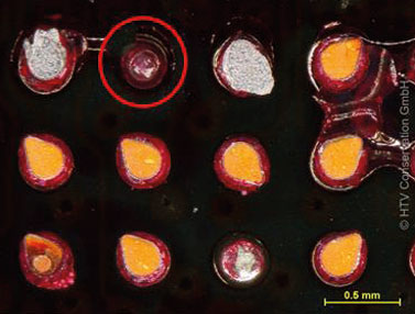
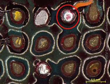
Every solder joint of a BGA, say, to locate interruptions or evaluate the general solder joint quality in regards to fracture formation, may be analyzed using the Dye & Pull test, also known as Dye & Pry test.
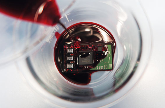
The assembly’s area suspected to contain a flawed component is dyed with a specialized dye, and then the dye is, for all intents and purposes, forced into possible defects like fractures or head-in-pillow defects by exposing the assembly to a vacuum. After mechanically pulling (or prying) the component from the assembly the solder joints may now be visually inspected and examined for possible dye residue on fractures.
The Dye & Pull test makes it possible to discover interruptions which might escape an x-ray inspection because of either their very small expansion (hairline fractures) or because they were covered by other components on the assembly’s opposite side.